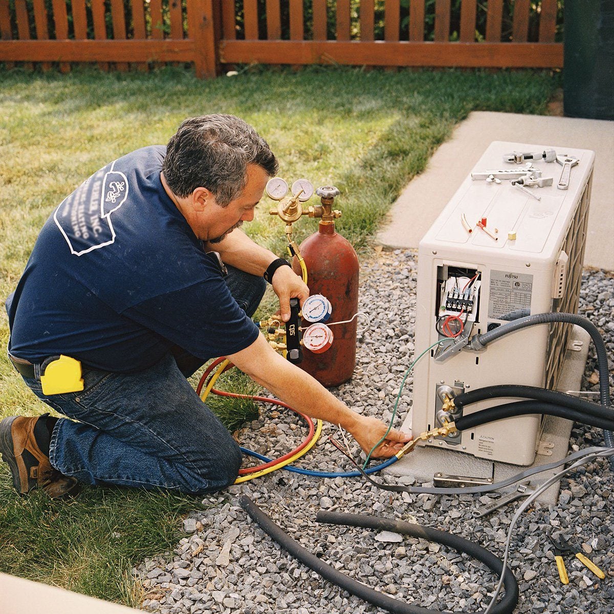
A mini-split installation can look deceptively simple. Hang an indoor unit, place an outdoor unit, connect ry. In reality, every successful job depends on dozens of small decisions made before, during, and after installation.
The best contractors understand that technical performance and customer satisfaction are inseparable. A perfectly evacuated refrigerant circuit will not impress a homeowner if the indoor unit whistles above the bed, the condensate drips onto the patio, or nobody explains why the heat pump occasionally enters defrost mode. Conversely, a friendly technician cannot charm away poor sizing, damaged flare connections, or an outdoor unit buried under snow.
These mini-split installation tips cover system design, equipment selection, placement, refrigerant piping, drainage, electrical work, commissioning, and customer education. The goal is not merely to make the system turn on. The goal is to make it perform correctly for years while keeping callbacks, complaints, and awkward conversations to a minimum.
Start With Design, Not a Drill
Installation success begins long before anyone opens a toolbox. The design phase determines whether the equipment will match the building, the climate, and the homeowner’s expectations.
Perform a Real Heating and Cooling Load Calculation
Do not size a mini-split solely by square footage. Two rooms with identical floor areas can have dramatically different loads. A shaded bedroom with insulated walls is not the same as a west-facing sunroom filled with windows, even when both measure 300 square feet.
A proper residential load calculation considers insulation, air leakage, windows, orientation, occupancy, appliances, ceiling height, local design temperatures, and other building characteristics. ACCA Manual J is the recognized residential load-calculation standard, while Manual S helps contractors select equipment based on calculated loads and actual manufacturer performance data. sizing is especially problematic with mini-splits. Although inverter-driven compressors can reduce capacity, every unit has a minimum operating range. An oversized system may cycle unnecessarily, remove less humidity, create temperature swings, and cost more upfront. Bigger is not automatically better; sometimes it is simply bigger.
Evaluate Both Maximum and Minimum Capacity
Look beyond the large capacity number printed on the sales brochure. Review the manufacturer’s performance tables at the outdoor temperatures expected in the project’s climate.
For heating applications, confirm how much capacity the system can deliver at winter design conditions. For mild-weather performance, examine minimum capacity. A unit that cannot turn down low enough may cycle during spring and fall, particularly in small, efficient rooms.
Cold-climate projects deserve additional attention. Product databases and performance specifications can help contractors compare output at low outdoor temperatures rather than relying only on nominal ratings. Properly Matched Components
Indoor and outdoor units should form an approved manufacturer combination. Mixing components because the connections appear compatible can affect efficiency, controls, capacity, warranty coverage, and reliability.
For multi-zone systems, verify allowable indoor-unit combinations, connected capacity limits, line-length restrictions, branch-box requirements, and diversity rules. Do not assume that connecting three indoor units produces the same performance as three independent single-zone systems.
AHRI certification information can help verify matched equipment combinations and rated performance. Proper matching is fundamental to receiving the efficiency and durability the customer expects. duct a Thorough Site Survey
A careful walkthrough prevents surprises that otherwise appear at the least convenient moment, usually after the ladder is set up and the homeowner has moved an antique cabinet into the work area.
Plan Indoor Unit Placement
Choose a location that allows conditioned air to circulate throughout the intended zone. Avoid placing a wall-mounted head where curtains, tall furniture, beams, or cabinets will obstruct airflow.
Also consider how the room is used. An indoor unit directly above a bed or favorite chair may create an uncomfortable draft. A unit near a cooking appliance, television, lamp, or sunny window may sense heat that does not represent the average room temperature.
Confirm all manufacturer-required clearances for the ceiling, side walls, service access, and filter removal. The prettiest location is not always the most serviceable one. A technician should be able to open the unit, clean the blower wheel, inspect connections, and remove components without performing advanced furniture gymnastics.
Select a Stable Outdoor Location
The outdoor unit needs free airflow, drainage, structural support, and reasonable service access. Follow the manufacturer’s required clearances rather than squeezing the condenser into a decorative enclosure designed by someone who believes compressors breathe through positive thinking.
Install the unit on a solid pad, approved wall bracket, or properly designed stand. In snowy climates, elevate it above expected accumulation and keep it away from roof-slide zones. Account for water released during defrost so it does not freeze across a walkway or form an ice pedestal beneath the unit.
Avoid locations where dryer exhaust, grease, leaves, or roof runoff can foul the coil. When possible, reduce noise transmission by keeping the unit away from bedroom walls and using mounting methods appropriate for the structure.
Map the Entire Line-Set Route
Before drilling, identify framing, plumbing, electrical wiring, exterior finishes, drainage paths, and access limitations. Confirm the total line length and vertical separation against manufacturer limits.
Plan graceful bends rather than sharp turns. Refrigerant tubing should not be kinked, flattened, or repeatedly bent in the same place. Decide where line-hide channels, covers, disconnects, and condensate outlets will go so the finished job looks intentional rather than improvised.
Make Drainage Boring and Reliable
Condensate problems are among the fastest ways to turn a happy customer into an amateur indoor-waterfall critic.
Gravity drains need a continuous downward pitch, adequate support, and no sags that trap water. Avoid uphill sections, compressed hoses, loose connections, and termination points that can clog with soil or insects. Manufacturer instructions commonly require downward-sloping drain piping and a functional drainage test before the job is completed. late drain sections when condensation may form on the outside of the tubing. Where gravity drainage is impossible, choose a condensate pump sized and installed for the application. Mount it to limit vibration, provide maintenance access, and test its safety switch.
Before leaving, pour water into the drain pan as directed by the manufacturer. Confirm that it flows freely, exits at the correct location, and does not leak inside the wall. Five minutes of testing can prevent a ceiling repair and a deeply unpleasant telephone call.
Treat Refrigerant Piping as Precision Work
Keep Tubing Clean and Dry
Cap open copper tubing immediately. Moisture, dirt, metal filings, and construction debris do not belong inside a refrigeration system. Cut tubing with an appropriate tubing cutter, remove burrs carefully, and prevent debris from falling into the pipe.
Use the line sizes specified by the equipment manufacturer. Confirm whether additional refrigerant is required for line lengths beyond the factory-charge allowance, and calculate the amount using the manufacturer’s instructions.
Create High-Quality Flare Connections
Flare joints are common leak points, but they are not inherently unreliable when prepared correctly. Use the correct flare tool for the tubing and refrigerant application. Inspect the finished flare for cracks, uneven edges, scratches, excessive thinning, and incorrect dimensions.
Align the connection before threading the nut by hand. Use a backup wrench and a calibrated torque wrench, tightening to the exact value specified for the model and tube size. Both under-tightening and over-tightening can cause leaks. Manufacturer installation manuals repeatedly emphasize proper flare preparation and torque-wrench use. ot apply sealants, oils, or additives unless the current manual specifically calls for them. Procedures differ among manufacturers and refrigerants, so yesterday’s habit should not overrule today’s instructions.
Pressure-Test Before Evacuation
After the piping is connected, perform a pressure test with dry nitrogen according to the manufacturer’s procedure. Use a regulated nitrogen supply and verify joints with an approved leak-detection method.
Allow enough time to determine whether pressure is stable while accounting for temperature changes. A quick glance at the gauge is not the same as a completed standing-pressure test. Finding a leak before evacuation is far easier than discovering it after refrigerant has been released into the lines.
Evacuate With Accurate Instruments
Use clean, vacuum-rated hoses, a quality vacuum pump, a core-removal tool where appropriate, and a calibrated micron gauge placed away from the pump. The manifold’s compound gauge is not a substitute for a micron gauge.
Evacuate to the target specified by the manufacturer, isolate the system, and conduct a decay test. A stable reading helps confirm that moisture and major leaks have been addressed. If the vacuum rises excessively, investigate rather than declaring the micron gauge overly emotional.
In the United States, work that can release refrigerantincluding adding or removing refrigerant and connecting service equipment to the refrigerant circuitgenerally requires EPA Section 608 technician certification. State licensing, permits, and local codes may impose additional requirements. the Electrical Details Right
Confirm voltage, minimum circuit ampacity, maximum overcurrent protection, disconnect requirements, conductor size, grounding, and communication-wire specifications from the nameplate, installation manual, and applicable code.
Many mini-split systems use polarity-sensitive communication wiring between the outdoor and indoor units. Label conductors and verify terminal-to-terminal consistency. A wire that lands on terminal two outdoors should not become terminal three indoors because it took a creative journey through the wall.
Tighten terminals to specified torque, protect wiring from sharp edges, install strain relief, and keep communication wiring separated as required. Before energizing the equipment, recheck voltage and inspect every termination.
Commission the System Instead of Merely Starting It
A system that powers on has passed one test: it powers on. Commissioning determines whether it operates as designed.
Follow the manufacturer’s startup procedure and allow the system to stabilize. Test every indoor unit in heating, cooling, fan, dry, and other applicable modes. For multi-zone equipment, test individual and simultaneous operation.
Record relevant measurements, including:
- Model and serial numbers
- Line-set lengths and vertical separation
- Additional refrigerant charge, when applicable
- Pressure-test conditions and results
- Final vacuum and decay-test readings
- Supply voltage and operating amperage
- Indoor and outdoor temperatures
- Temperature split and airflow observations
- Condensate-drain test results
- Control, sensor, and error-code checks
Field studies and contractor guidance emphasize that installation, sizing, controls, and commissioning can significantly affect heat-pump performance, energy use, reliability, and customer satisfaction. en for vibration and refrigerant-line contact. Inspect insulation, wall penetrations, covers, fasteners, and weather sealing. Confirm that all service caps are tightened according to the manual and that valves are in the correct operating position.
Make the Finished Installation Look Professional
Customers notice appearance before they notice micron readings. Keep line-hide channels straight, seal wall penetrations neatly, trim excess materials, remove fingerprints, and clean the work area.
Outdoor tubing should be fully insulated and protected from weather, animals, ultraviolet exposure, and physical damage. Do not leave cable ties, scraps of copper, packaging, or mystery screws scattered around the property.
Take photographs of the completed indoor and outdoor installations, electrical connections, equipment labels, line routes, and commissioning instruments. These images help with warranty registration, future service, quality control, and disputes about what was installed.
Turn the Homeowner Handoff Into a Mini Training Session
Do not hand over the remote control as though it were the key to a rental car. Spend a few minutes teaching the customer how the system behaves.
Demonstrate mode selection, temperature settings, fan speeds, vane positions, timers, Wi-Fi controls, filter removal, and basic cleaning. Explain that “auto” mode may switch between heating and cooling, which can be undesirable during mild weather or in multi-zone applications.
Set realistic expectations. Heat pumps often deliver steady, moderate-temperature air rather than the brief blast of very hot air associated with some furnaces. During heating operation, the outdoor unit may produce water, steam, or temporary pauses as part of normal defrost operation.
Explain recommended filter-cleaning intervals, outdoor-unit clearance, and professional maintenance needs. Give the customer model numbers, warranty information, manuals, installer contact details, and a commissioning report. Clear communication reduces unnecessary service calls and builds confidence in the installation.
Common Mini-Split Installation Mistakes to Avoid
- Sizing equipment by square footage alone
- Ignoring minimum capacity and low-load cycling
- Using unapproved indoor and outdoor unit combinations
- Installing indoor heads where furniture blocks airflow
- Placing outdoor units where snow, runoff, or vegetation obstructs them
- Creating condensate traps or uphill drain sections
- Reusing damaged flare nuts or poorly formed flares
- Tightening flare joints by feel instead of measured torque
- Skipping the nitrogen pressure test
- Evacuating without a micron gauge or decay test
- Guessing at additional refrigerant charge
- Miswiring indoor-to-outdoor communication terminals
- Skipping documentation and homeowner instruction
Field Experience: Lessons Behind Successful Installations
Real-world installation experience shows that callbacks rarely begin with one spectacular mistake. More often, they result from a chain of small oversights. The bracket is slightly out of level, the drain hose develops a shallow sag, insulation is compressed behind the wall sleeve, and nobody pours water into the pan. The unit cools perfectly for two weeksuntil humid weather arrives and water appears on the drywall.
Experience 1: The Quiet Bedroom That Was Not Quiet
Consider a bedroom installation where the equipment operates within its published sound rating, but the homeowner still complains at night. The problem may be structural vibration rather than fan noise. An outdoor unit mounted on lightweight siding near the bedroom can transmit a low-frequency hum through the framing.
The lesson is to discuss sound sensitivity during the site survey. A ground stand, a different wall, appropriate isolation materials, or a slightly longer line route may produce a happier result than choosing the shortest possible installation path.
Experience 2: The Oversized Sunroom System
A glass-heavy sunroom may have a large afternoon cooling load but a much smaller load during mild weather. Selecting equipment only for the hottest hour can create frequent cycling throughout the rest of the season.
Successful contractors compare maximum and minimum capacities, discuss shading options, and explain the comfort tradeoffs. Sometimes the best solution combines properly selected equipment with window treatments or modest building-shell improvements rather than asking the mini-split to fight the sun in single combat.
Experience 3: The Mystery Water Leak
A system may pass a quick drainage check and still leak later if the drain line is unsupported. As the tubing warms, cools, and fills with water, a soft section can sag and create a trap. Slime and debris then collect in the low spot until the drain backs up.
Experienced installers support the line continuously, maintain a visible downward pitch, insulate it where necessary, and confirm the discharge point. They also show the homeowner where the water exits so a blocked termination can be recognized before it becomes an indoor problem.
Experience 4: The Refrigerant Leak That Looked Fine on Day One
A flare connection tightened by feel may hold during startup but leak after repeated heating and cooling cycles. Copper expands, contracts, and vibrates. A scratched flare face or distorted joint can slowly lose refrigerant even though no obvious leak appeared during a rushed inspection.
The practical lesson is wonderfully unglamorous: use clean tools, inspect the flare, use a backup wrench, apply the specified torque, pressure-test, and document the result. Good refrigeration work is often invisible, which is exactly how customers prefer it.
Experience 5: The Customer Who Thought Defrost Was a Breakdown
In winter, a homeowner may see steam rising from the outdoor unit, hear a change in operating sound, and notice that indoor airflow pauses. Without an explanation, these normal defrost behaviors can look like a dramatic mechanical failure.
A two-minute demonstration during handoff can prevent an unnecessary emergency call. Explain normal noises, defrost cycles, outdoor drainage, filter maintenance, remote-control symbols, and when the customer genuinely should request service.
The broad lesson from successful projects is that workmanship and communication reinforce each other. Careful design makes installation easier. Careful installation makes commissioning predictable. Thorough commissioning makes the homeowner handoff confident. A confident customer is more likely to maintain the system properly, recommend the contractor, and call the same company for future work.
Conclusion
Mini-split installation success comes from following a repeatable process rather than relying on speed, habit, or guesswork. Calculate the load, select a properly matched system, plan each unit’s location, protect the refrigerant circuit, build dependable drainage, follow electrical requirements, and commission every operating mode.
Finally, treat customer education as part of the installationnot as an optional farewell speech. A system that is sized correctly, installed carefully, documented thoroughly, and clearly explained creates comfortable rooms, fewer callbacks, stronger reviews, and happier customers. That is a considerably better outcome than receiving a Sunday morning photograph of water running down freshly painted drywall.