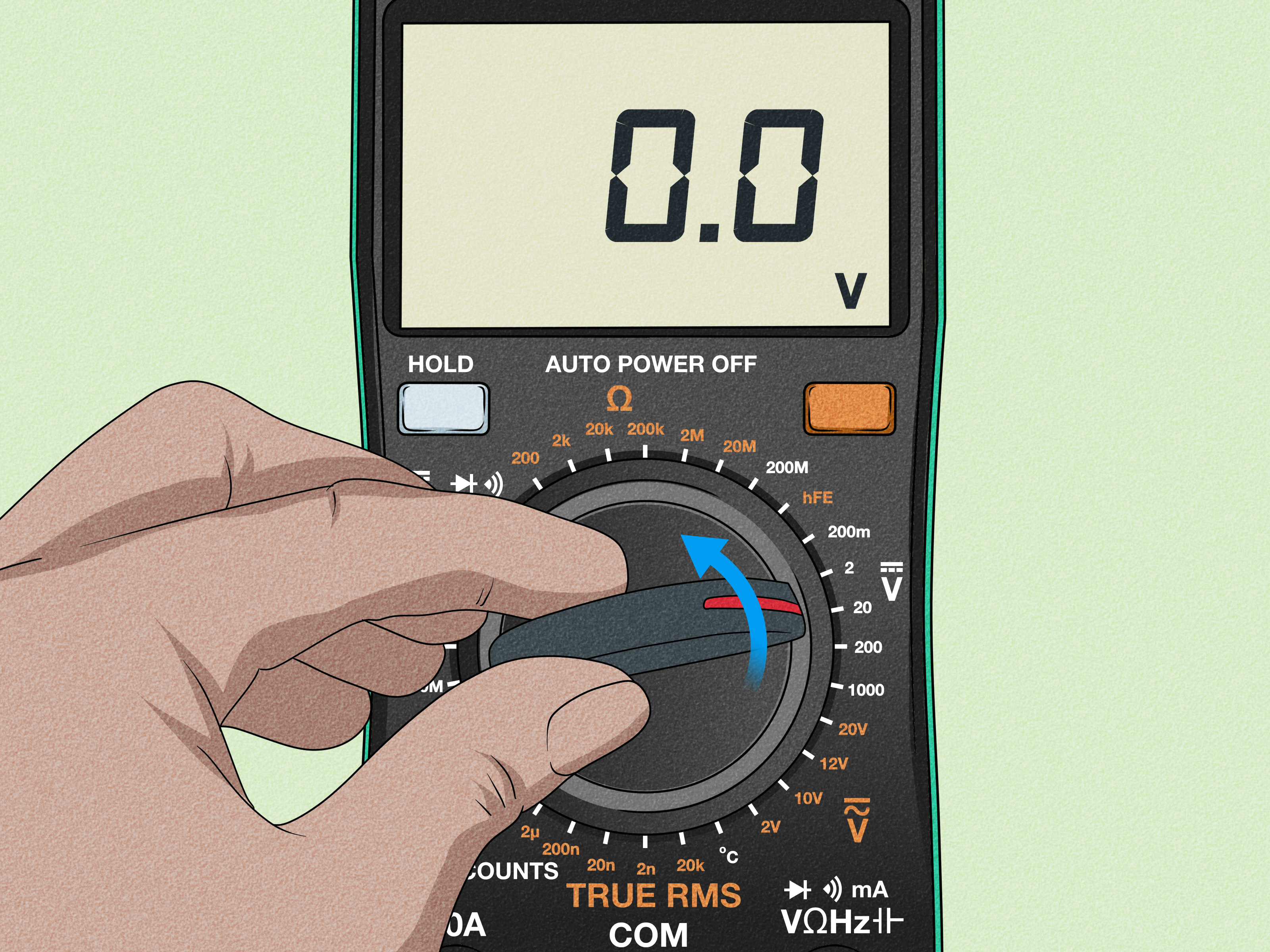
A digital ohm meter can look deceptively simple: touch two probes to a component, stare at the screen, and wait for a number to appear. Then the display flashes 4.72, 0.003, or the mysterious OL, and suddenly the meter appears to be communicating in robot riddles.
Fortunately, learning how to read a digital ohm meter is mostly about understanding three things: the displayed number, the measurement unit, and the warning symbols. Once those pieces click into place, you can test resistors, wires, switches, fuses, heating elements, and many other components without treating every decimal point as a personal attack.
Research synthesis:
What Does a Digital Ohm Meter Measure?
A digital ohm meter, commonly called a digital ohmmeter, measures electrical resistance. Resistance describes how strongly a material or component opposes the flow of electric current. Its standard unit is the ohm, represented by the Greek letter omega: Ω.
Most people do not purchase a separate ohmmeter. Instead, they use the resistance function built into a digital multimeter. A typical digital multimeter can measure voltage, current, resistance, and continuity, while more advanced models may also test capacitance, frequency, temperature, and diodes.
How the meter calculates resistance
When placed in resistance mode, the meter sends a small, controlled current through the component under test. It measures the resulting voltage and uses Ohm’s law to calculate resistance. In simplified form:
Resistance = Voltage ÷ Current
This internal test current is why a resistance measurement must be taken on a de-energized circuit. An outside voltage source interferes with the calculation and may damage the meter.
Common resistance units
Digital meters use metric prefixes to keep large resistance values readable:
- 1 Ω means one ohm.
- 1 kΩ means one kilo-ohm, or 1,000 ohms.
- 1 MΩ means one megaohm, or 1,000,000 ohms.
Therefore, a display reading of 4.7 kΩ equals 4,700 ohms. A reading of 2.2 MΩ equals 2,200,000 ohms. The small unit symbol matters enormously. Ignoring it is like reading “5 miles” as “5 feet” and wondering why the road trip ended in the driveway.
Research synthesis:
Prepare the Meter Before Reading Resistance
Accurate interpretation begins with correct setup. A perfectly readable number is not useful when the probes are plugged into the wrong terminals or the circuit is still energized.
Turn off and isolate the power
Disconnect the device from its power source before measuring resistance. Remove batteries when practical, unplug equipment, and follow proper lockout procedures when working on machinery or building wiring. Components such as capacitors can retain stored energy even after power has been removed, so high-voltage capacitors must be safely discharged according to the equipment manufacturer’s instructions.
Never switch a meter to resistance mode and place it across a live household circuit. That is not an adventurous shortcut; it is misuse of the instrument and can expose the user to shock, arc hazards, equipment damage, or all three.
Connect the probes correctly
Insert the black probe into the port marked COM. Insert the red probe into the port marked with VΩ, Ω, or a combination of voltage, resistance, and diode symbols.
Do not leave the red probe in the high-current or amp terminal. Before every measurement session, take two seconds to check the ports. That tiny habit prevents a surprisingly large collection of expensive noises.
Select resistance mode
Turn the selector dial to the Ω position. Some multimeters combine resistance, continuity, capacitance, and diode testing at one dial position. On these meters, press the SELECT, MODE, or similar button until the Ω symbol appears on the display.
Check the test leads
Touch the two probe tips together. A functioning meter should display a value at or close to zero ohms. A small reading, such as 0.1 or 0.3 Ω, may represent the resistance of the leads and their contact points.
If the meter continues to show OL with the probes firmly touching, inspect the leads, confirm the selected function, and check the meter’s battery. Dirty or damaged probe tips can also create unreliable readings.
Safety and setup references:
Way 1: Read Resistance in Plain Ohms
The first and easiest method applies when the meter displays the Ω symbol without a k or M prefix. In this case, the displayed number is read directly in ohms.
Example: Testing a small resistor
Suppose the display reads:
47.6 Ω
The measured resistance is 47.6 ohms. No multiplication is required.
Other examples include:
- 0.4 Ω = four-tenths of an ohm
- 12.8 Ω = 12.8 ohms
- 680 Ω = 680 ohms
- 999 Ω = 999 ohms
Understanding very low readings
A reading close to zero generally indicates a low-resistance path. That may be exactly what you expect from a short wire, closed switch, good fuse, or solid connection. However, it may indicate an unwanted short circuit when testing between two points that should be electrically isolated.
For low-resistance measurements, first touch the probes together and note the lead resistance. If the shorted probes read 0.2 Ω and the component reads 0.5 Ω, the component itself may contribute approximately 0.3 Ω. Some meters provide a REL or relative function that automatically subtracts the initial lead reading.
Use the expected value as context
A number is meaningful only when compared with an expected result. A reading of 8 Ω may be normal for a speaker, unusually high for a short jumper wire, or suspiciously low for a 10-kΩ resistor. The meter reports the measurement; it does not know whether the component is behaving itself.
Direct resistance reading references:
Way 2: Convert kΩ and MΩ Readings
The second way to read a digital ohm meter is to identify the metric prefix and convert the displayed value when necessary. This is where many beginners misread a perfectly good result by a factor of 1,000or occasionally 1,000,000, for those who prefer their mistakes in bulk.
Reading kilo-ohms
When the screen displays kΩ, multiply the number by 1,000 to convert it to ohms.
- 1.00 kΩ = 1,000 Ω
- 2.20 kΩ = 2,200 Ω
- 4.70 kΩ = 4,700 Ω
- 47.5 kΩ = 47,500 Ω
- 680 kΩ = 680,000 Ω
Electronics documentation often places the prefix where a decimal would otherwise appear. For example, 4k7 means 4.7 kΩ, and 2k2 means 2.2 kΩ.
Reading megaohms
When the screen displays MΩ, multiply the displayed number by 1,000,000.
- 1.00 MΩ = 1,000,000 Ω
- 2.20 MΩ = 2,200,000 Ω
- 0.500 MΩ = 500,000 Ω, or 500 kΩ
- 0.047 MΩ = 47,000 Ω, or 47 kΩ
Reading an auto-ranging meter
An auto-ranging digital ohmmeter chooses an appropriate range automatically. You select Ω mode, connect the probes, and allow the reading to settle. Watch the unit indicator because the meter may move between Ω, kΩ, and MΩ while searching for the best range.
For example, the display may briefly show 0.98 MΩ before settling at 982 kΩ. Those values represent approximately the same resistance; the second format simply provides more useful resolution.
Reading a manual-ranging meter
A manual-ranging meter requires you to select a range such as 200 Ω, 2 kΩ, 20 kΩ, 200 kΩ, or 2 MΩ. When the resistance is unknown, begin with the highest available range and move downward until the meter provides a stable reading with useful digits.
If a resistor is approximately 4.7 kΩ, the 20-kΩ range is generally more appropriate than the 200-kΩ range because it displays greater detail. The 2-kΩ range is too low and will normally produce an over-range indication.
Unit, range, and tolerance references:
Way 3: Interpret OL, Zero, and Unstable Readings
The third method is learning to read the meter’s behavior, not merely its numbers. Error symbols and changing values often reveal more about a circuit than a tidy, stationary measurement.
What does OL mean on an ohm meter?
OL commonly means overload, over limit, or an open circuit, depending on the meter and the situation. It appears when the resistance exceeds the selected range or when no conductive path exists between the probes.
On a manual-ranging meter, OL may simply mean the chosen range is too low. Move to a higher resistance range and test again. If the meter still shows OL on its highest range, the component or path is probably open or has resistance beyond the meter’s capability.
Some meters display a lone 1, dashed lines, or another symbol instead of OL. Consult the meter’s manual because manufacturers do not always speak the same dialect of electronic disappointment.
What does a zero or near-zero reading mean?
A reading near 0 Ω means the probes are connected through a very low-resistance path. Common examples include:
- A good fuse
- A closed mechanical switch
- A short piece of copper wire
- A direct short between test points
- A component that has failed shorted
Do not automatically label every near-zero result “good.” The correct interpretation depends on what the circuit should be doing.
Why does the reading keep changing?
A fluctuating resistance reading can have several causes. The probe tips may not be making firm contact. Oxidation, paint, oil, dirt, or corrosion may be interfering with the connection. Your fingers may also be touching both conductive probe tips, allowing the meter to include your body’s resistance in the measurement.
Some components naturally change resistance. Thermistors respond to temperature, photoresistors respond to light, and potentiometers change as their shafts or sliders move. A rising or falling reading is not always an error; sometimes the component is simply doing its job.
Why in-circuit measurements can be misleading
When a resistor remains connected to a circuit board, the meter measures every available path between the probes. Other components connected in parallel can lower the displayed resistance. As a result, an in-circuit reading may be less than the resistor’s marked value even when the resistor is perfectly healthy.
For a more dependable measurement, disconnect at least one resistor lead from the circuit. This isolates the component so the meter measures the resistor rather than the resistor plus the rest of the electronic neighborhood.
Display interpretation and in-circuit references:
How to Decide Whether a Resistance Reading Is Good
After reading the display correctly, compare the result with the component’s expected value and tolerance. A 1-kΩ resistor with a 5% tolerance may normally measure between approximately 950 Ω and 1,050 Ω. A reading of 997 Ω would be comfortably within that range.
Temperature, meter accuracy, probe contact, manufacturing tolerance, and circuit connections can all affect the result. Do not condemn a component because the final digit wiggles slightly. Digital displays can show more digits than the situation meaningfully requires.
Quick interpretation guide
| Meter Display | Likely Meaning | Recommended Action |
|---|---|---|
| 0.0 to a few tenths of an ohm | Very low resistance or probe-lead resistance | Short the probes and compare the baseline |
| Stable value near specification | Component is probably within tolerance | Confirm tolerance and test conditions |
| OL on a manual range | Range may be too low | Select a higher range |
| OL on the highest range | Open circuit or extremely high resistance | Check connections and component continuity |
| Reading lower than expected in circuit | Parallel current paths may be present | Disconnect one component lead and retest |
| Reading jumps continuously | Poor contact or a variable component | Clean, secure, and repeat the measurement |
Measurement evaluation references:
Practical Experience: Lessons Learned at the Workbench
Real-world resistance testing rarely looks as neat as the diagrams in an instruction manual. The probes slip, component markings fade, and the meter chooses the exact moment you look away to change from kΩ to MΩ. Several practical lessons make the process faster and far less frustrating.
Lesson 1: Read the unit before trusting the number
One of the most common beginner experiences is measuring a resistor, seeing 4.68, and assuming the resistor is only 4.68 Ω. A glance at the corner of the display reveals the tiny kΩ indicator, changing the correct answer to 4,680 Ω. The digits were accurate; the interpretation was not.
A useful habit is to say the complete result aloud or silently: “four point six eight kilo-ohms.” This forces your brain to process the prefix instead of staring only at the large numbers.
Lesson 2: A stable connection is worth more than dramatic probe pressure
Pressing the probes harder is not always the solution to an unstable reading. Probe tips can slide off small component leads, and heavy pressure may bend the component or damage a circuit-board pad. Alligator clips, hook probes, or fine-point accessories often provide a much more repeatable connection.
For oxidized terminals, gently cleaning the contact point can transform a jumping display into a stable measurement. The meter cannot measure through layers of corrosion by sheer optimism.
Lesson 3: Fingers can become part of the circuit
When measuring high resistance, holding a metal probe tip in each hand can create a parallel path through your skin. The effect may be minor on a low-value resistor but significant when testing values in the megaohm range.
Hold the probes by their insulated sections. For small loose components, place the part on a nonconductive surface or secure it with clips. This improves safety, stability, and repeatability.
Lesson 4: An in-circuit result is often a clue, not a verdict
Imagine testing a resistor marked 10 kΩ while it remains soldered to a circuit board. The meter reports 6.3 kΩ. It is tempting to declare the resistor defective, but another resistor, transistor junction, or circuit path may be connected in parallel.
After lifting one resistor lead, the meter may display 9.96 kΩ, proving that the original component was fine. Experienced troubleshooters use in-circuit measurements as quick screening tests, then isolate suspicious components before reaching a final conclusion.
Lesson 5: Start with a known component
Before diagnosing an unfamiliar appliance or circuit, test the meter on a known resistor. A 1-kΩ or 10-kΩ resistor makes a convenient reference. This simple check confirms that the probes, ports, battery, dial position, and range selection are working together correctly.
It also builds confidence. When the known 10-kΩ resistor reads approximately 9.9 or 10.1 kΩ, you know the meter is not inventing numbers for entertainment.
Lesson 6: Low resistance requires extra skepticism
When measuring a component with only a fraction of an ohm, ordinary probe and contact resistance may represent a large portion of the final result. Shorting the probes and using a relative function can improve a basic two-wire measurement.
For precision work, long leads, shunts, motor windings, or other very low-resistance components, a four-wire or Kelvin measurement is more appropriate. This method uses one pair of leads to supply test current and another pair to sense voltage directly across the component, greatly reducing errors caused by lead and contact resistance.
Lesson 7: Repeat suspicious measurements
A single surprising reading should lead to a second test, not an immediate parts order. Remove and reconnect the probes, reverse their positions, select the range again, and confirm that power is disconnected. Compare the result with a known-good component or another meter when available.
Resistance troubleshooting rewards patience. Most confusing results come from incorrect units, poor connections, parallel paths, wrong range selection, or a probe plugged into the wrong portnot from mysterious electrical forces plotting against the repair.
Practical measurement references:
Conclusion
Learning how to read a digital ohm meter becomes straightforward when you use three approaches. First, read plain Ω values directly. Second, convert kΩ and MΩ readings by paying close attention to the unit prefix. Third, interpret OL, near-zero, and unstable displays according to the selected range and the circuit’s expected behavior.
Always disconnect power, use the COM and VΩ terminals, confirm the Ω mode, and check the probes before testing. When a result seems suspicious, consider component tolerance, lead resistance, surface contamination, and parallel circuit paths before deciding that a part has failed.
Note: This article is intended for general education. Follow the instructions and safety ratings supplied with your specific meter, and leave testing on hazardous electrical systems to properly trained and qualified professionals.